How should a VRF refrigerant leak be found and repaired?
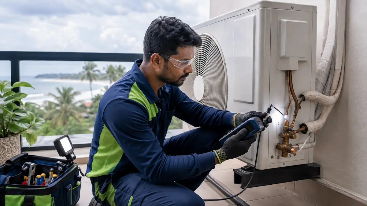
A VRF leak process should confirm charge-related evidence, review service history and alarms, map the refrigerant network, inspect oil or corrosion signs, use compatible electronic or bubble detection, and isolate sections when needed. After locating the leak, recover refrigerant as required, repair by approved procedure, pressure-test the repaired circuit, evacuate and weigh the calculated charge. Record leak location, repair and final system test; do not repeatedly top up an unknown leak.
Start with the network map and service history
Large VRF systems contain many joints, branches, indoor coils, outdoor modules and long concealed routes. Leak detection must be planned to avoid unnecessary ceiling opening and loss of evidence.
In humid Chidambaram conditions, coastal corrosion and wet insulation can affect exposed joints, but leaks may also occur at flares, brazed joints, valves or coils. Preserve alarm data, previous charge additions and affected-zone patterns before isolating sections.
Chidambaram experiences hot, humid conditions with seasonal dust and rain. AC decisions should consider room use, closure periods, drainage, outdoor exposure and the condition found during inspection.
What to check before approving work
Start with safe, observable conditions and move to model-specific technical tests only when the evidence requires them.
Confirm the symptom
Review pressures, temperatures, charge history, alarms and affected zones with airflow established.
Map the circuit
Use as-built pipes, branches, isolation options, charge calculation and access points.
Prioritize likely locations
Inspect joints, valves, coils, corrosion, oil traces and disturbed sections with suitable methods.
Professional checks for VRF Refrigerant Leak Detection
Detection plan
Define tools, sections, access, occupied-area controls and manufacturer procedures.
Safe refrigerant handling
Use trained personnel and appropriate recovery, ventilation and refrigerant-specific practices.
Repair and integrity test
Complete approved joint or component repair followed by documented pressure/leak testing.
Evacuation and charge
Dehydrate the circuit and weigh the calculated charge before commissioning.
VRF leak evidence and the next investigation step
One symptom can have several causes. Use the pattern, timing and accompanying signs to narrow the next test instead of replacing parts from a guess.
The table is a decision aid, not a substitute for model-specific procedures, safe instruments or manufacturer service information.
| Evidence | Possible meaning | Next action |
|---|---|---|
| Repeated charge additions | Unresolved leak or service loss | Review records and map circuit |
| Oil at a joint | Possible leak location | Clean and confirm with approved test |
| One branch affected | Localized valve, coil or branch issue | Use topology and isolation evidence |
| Whole system underperforms | Charge, airflow, capacity or controls | Confirm system-wide diagnostics |
Refrigerants can displace oxygen and may have flammability or pressure hazards depending on type. Follow product, manufacturer and applicable safety requirements.
What records should close a VRF leak repair?
The final test should reproduce the original operating condition as closely as practical and show whether the reported problem is resolved.
Record the work completed, relevant readings, parts used and any remaining limitation so a future visit starts with evidence rather than assumptions.
- Leak location and detection method are recorded.
- Repair method and affected component are identified.
- Pressure and standing-test results are retained.
- Evacuation and weighed charge are documented.
- All zones and alarms are checked after commissioning.
From first observation to verified handover
- 1
Confirm and map
Review operating evidence, history and as-built network.
- 2
Search systematically
Inspect and test prioritized joints, valves, coils and sections.
- 3
Isolate when needed
Narrow large networks using manufacturer-approved section strategies.
- 4
Repair and prove integrity
Complete approved repair and documented pressure/leak test.
- 5
Evacuate, charge and commission
Weigh charge and verify the complete system.
Plan occupied-building access before leak testing
Coordinate ceiling access, room closures, detectors, ventilation, hot-work controls where applicable and protection of sensitive areas. Define who restores ceilings and finishes after the leak location is proven.
Keep refrigerant type, total calculated charge, previous additions and repair history in the asset register. Recurring loss at the same section may justify a wider replacement decision.
Ask what is included, what is excluded, which findings support additional work and how the final result will be tested.
Common mistakes to avoid
- Topping up refrigerant without finding the loss.
- Opening many ceilings before using the network map.
- Charging by pressure alone instead of the manufacturer calculation and procedure.
- Approving work without asking how the final result will be tested and recorded.
Frequently asked questions
How are leaks found in a large VRF system?
Technicians combine service history, diagnostics, network mapping, visual evidence, compatible detectors and section isolation where necessary.
Can pressure readings locate a VRF leak?
They may support a charge concern but do not identify the leak location. Direct detection and section testing are required.
Should VRF refrigerant be topped up every year?
No. A sealed system should not need routine top-up. Repeated loss requires leak investigation and repair.
Why must the final charge be weighed?
VRF charge depends on model, connected equipment and pipe lengths. Manufacturer calculation and weighed charging provide traceability.
What should a leak report include?
Include circuit, location, detection method, repair, pressure test, evacuation, charge, alarms and final zone operation.
Talk to Turbo Cooling Solutions
Share your location, AC type and requirement for a clear service response.