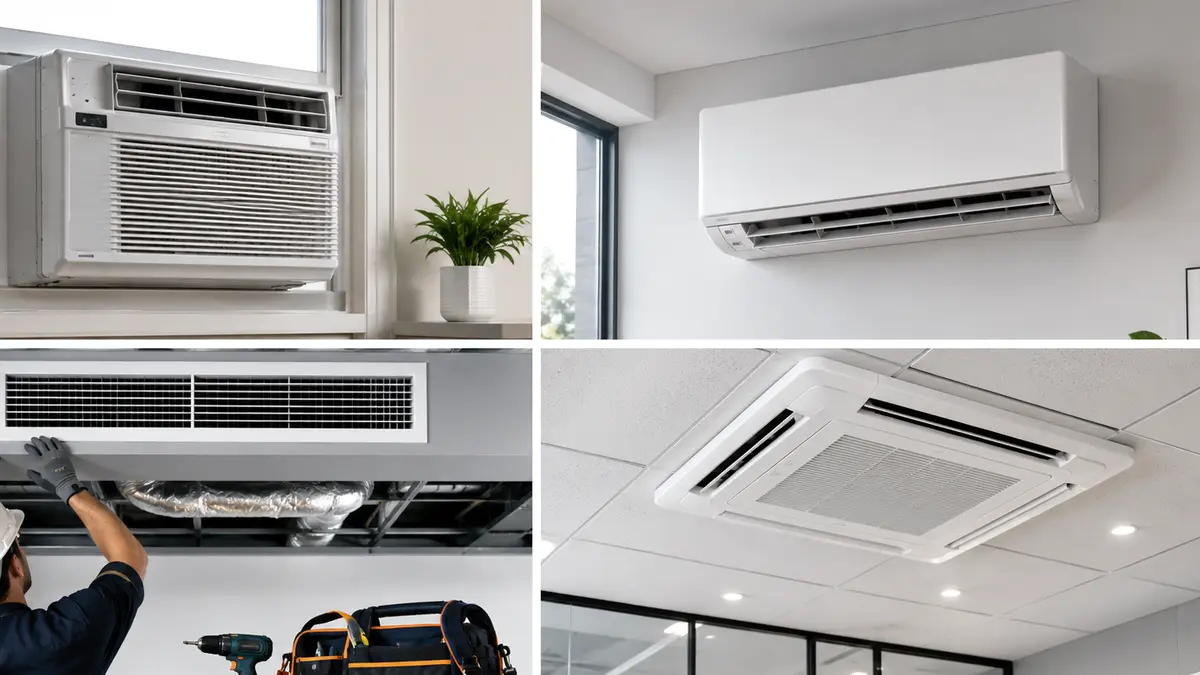
Why does one VRF indoor unit stay warm?
When one VRF indoor unit does not cool, first confirm controller mode, set point, schedule, central lockout and whether the system permits simultaneous operating requests. Then inspect filter, coil, fan, sensor, drain protection, electronic expansion valve command, addressing and communication. Compare the affected zone with healthy units on the same system before changing refrigerant charge, because a system-wide charge issue usually needs broader evidence.
Compare the affected zone with a healthy zone on the same network
VRF zones share outdoor capacity and a communication and refrigerant network. A local complaint can result from a room controller, indoor unit, branch component, operating conflict or system-level limitation.
Record address, controller state, room load, supply airflow, valve command and error history. In dusty Villupuram sites, filter and coil loading may be localized by use, but controls and branch relationships still need system-level review.
Villupuram homes and businesses can face strong seasonal heat, roadside dust and variable operating schedules. Filter loading, outdoor airflow and electrical conditions should be checked with the reported symptom.
What to check before approving work
Start with safe, observable conditions and move to model-specific technical tests only when the evidence requires them.
Command and permissions
Confirm mode, set point, schedule, centralized restrictions and simultaneous heat/cool rules.
Local air path
Check filter, coil, fan, louvers, return path and room sensor position.
Network and valve
Review address, communication, valve response, pipe temperatures and relevant fault data.
Professional checks for VRF Zone Cooling Diagnosis
Asset identity
Reconcile unit model, address, controller, branch and served room with as-built documents.
Zone measurements
Record return/supply conditions, fan command, room load and sensor reading.
System comparison
Compare valve, pipe and capacity behaviour with other zones and outdoor operation.
Final network test
Verify the repaired zone in representative simultaneous operation and confirm alarms clear correctly.
Warm VRF zone patterns and next tests
One symptom can have several causes. Use the pattern, timing and accompanying signs to narrow the next test instead of replacing parts from a guess.
The table is a decision aid, not a substitute for model-specific procedures, safe instruments or manufacturer service information.
| Pattern | Possible area | Next evidence |
|---|---|---|
| Fan off, controller on | Permission, motor or communication | Command and fault history |
| Good airflow but warm | Valve, branch or system capacity | Pipe temperatures and valve command |
| Zone cools outside peak hours | Load or capacity allocation | Room and network load trend |
| Several related zones warm | Branch or system-level issue | Topology and outdoor diagnostics |
Do not add refrigerant because one zone is warm. Use manufacturer diagnostics and system-wide evidence to confirm charge or leakage.
What proves the affected VRF zone is restored?
The final test should reproduce the original operating condition as closely as practical and show whether the reported problem is resolved.
Record the work completed, relevant readings, parts used and any remaining limitation so a future visit starts with evidence rather than assumptions.
- Controller demand reaches the correct address.
- Fan and airflow match command.
- Valve and pipe response are normal for the mode.
- Room temperature trends toward set point under known load.
- The zone remains stable with other indoor units operating.
From first observation to verified handover
- 1
Identify the zone
Confirm room, address, controller, branch and reported schedule.
- 2
Check permissions and air path
Review modes, lockouts, filter, fan, coil and sensor.
- 3
Read system diagnostics
Compare communication, valve and pipe behaviour across zones.
- 4
Correct the proven cause
Repair local or network faults without disturbing healthy zones.
- 5
Test combined operation
Verify the room under realistic system load.
Send the zone identity, not only the room name
Include controller photograph, asset label, address, floor plan location, operating schedule, error code and times when the zone fails. Note whether adjacent zones on the same branch cool normally.
Keep as-built drawings and service-software backups available. Accurate topology can reduce ceiling opening and unnecessary parts replacement.
Ask what is included, what is excluded, which findings support additional work and how the final result will be tested.
Common mistakes to avoid
- Adding system refrigerant for one warm zone without leak evidence.
- Resetting the whole network before saving error history.
- Ignoring central controller lockouts and mode conflicts.
- Approving work without asking how the final result will be tested and recorded.
Frequently asked questions
Why is one VRF room not cooling while others work?
Possible causes include local settings, lockout, filter, fan, sensor, valve, addressing, communication, branch issues or unequal room load.
Can one VRF indoor unit have low gas?
Indoor units share the refrigerant network. A local valve or branch problem may mimic charge trouble; system-wide evidence is required.
What is a VRF mode conflict?
Some systems or configurations cannot satisfy heating and cooling requests simultaneously, so one request may be restricted by system priority.
Should the entire VRF system be reset?
Preserve error history first. A reset can remove useful evidence and may disrupt healthy zones without correcting the fault.
How should the repair be verified?
Test controller response, airflow, valve and pipe behaviour, room trend and operation alongside other active zones.
Talk to Turbo Cooling Solutions
Share your location, AC type and requirement for a clear service response.